First, understand what changes
This guide concerns direct-view LED displays, not COB light engines used for illumination.
COB and SMD are common choices for meeting rooms, control rooms and indoor displays. They primarily describe how LED chips are packaged and mounted. Neither term alone determines the wall's resolution, weather protection, touch capability or final price. Start by defining the environment, nearest viewer, screen dimensions and content.
With SMD, LED chips are typically made into individual packaged devices before those devices are mounted onto a PCB. COB mounts and connects bare LED chips directly to a substrate before encapsulation. COB also includes different die-interconnection approaches; the label does not automatically specify a particular flip-chip construction.

Where SMD is useful—and what to check
One practical strength of SMD is its established component and assembly ecosystem, with choices of pitch, drivers and cabinet formats. Suitably equipped technicians can rework individual packages; this is a different service step from exchanging modules in the field to restore a display. For projects that value an existing spares system, repair resources and configuration choices, these are practical strengths to assess.
Small exposed packages can be vulnerable to contact during handling, assembly or everyday use. Finer pitches also place greater demands on package dimensions, placement accuracy and soldering. However, SMD does not necessarily mean an unprotected surface: some SMD platforms add protective coatings. Compare the construction actually supplied, rather than the acronyms alone.
What COB offers, and where the conditions matter
Direct die placement supports dense, fine-pitch layouts. Integral encapsulation also creates opportunities for surface protection, black-state appearance and optical uniformity. These make COB worth comparing for close viewing, fine text and installations exposed to contact. Direct chip-to-substrate thermal paths are another design opportunity, while wall-level power and temperature still depend on drivers, power supplies, brightness and cooling.
COB does not remove every trade-off. Encapsulation materials and optical layers affect reflections and appearance, while die rework, encapsulation quality and module matching require appropriate capabilities. Field service for either approach may involve swapping modules. Confirm whether removed modules support package- or die-level repair, who performs the work, and the turnaround time. Neither maintenance-free operation nor replacing an entire wall for one failed pixel should be assumed.
Compare the trade-offs that affect your project
The table describes common design considerations, not a ranking of every product. Integral packaging and an added surface coating are different concepts. A protection, optical or energy claim for one manufacturer's product should not become a promise for an entire technology category.
| Consideration | SMD | COB |
|---|---|---|
| Fine-pitch design | Package dimensions and placement requirements constrain very fine pitches; check the actual range. | Direct die placement supports dense layouts; pitch and resolution remain model-specific. |
| Surface protection | Exposed packages can be vulnerable to contact; some platforms add protective coatings. | Integral encapsulation can protect the surface; verify impact resistance, cleaning and complete-model protection. |
| Optical appearance | Check pitch, the mask and the calibrated image. | Integrated optical layers can improve black-state appearance or uniformity; check reflections and low-brightness detail. |
| Service and spares | Field service may use module exchange. Package-level rework needs suitable tools and skills; confirm matched spares. | Field service may use module exchange; confirm die-level repair support, matched spares and turnaround. |
| Power and temperature | Check drivers, power supplies, operating brightness and cooling. | Direct thermal paths offer design potential, not an automatic wall-level saving. |
| Cost | An established choice of configurations has value; include spares, installation and downtime. | Process, yield and scale affect quotations; the label alone does not determine total cost. |
| On-camera behaviour | Test with the intended processor and camera settings. | Still needs camera testing; not a guarantee against moiré or banding. |
Turn the application into acceptance criteria
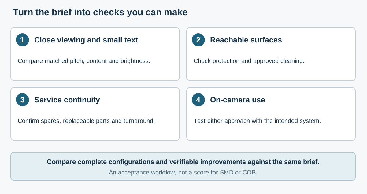
For close-viewed meeting-room text, establish pitch and representative content first. Then compare text edges, dark-grey detail, black-state appearance and off-axis viewing at the intended operating brightness. At the same pitch and display area, changing the label to COB does not add pixels; surface appearance and detail still need product-level assessment.
For a public display that people can reach, specify contact risks, cleaning procedures and the protection required for the complete installation. Compare suitably protected COB products as well as coated or otherwise protected SMD options. Packaging labels alone do not establish an IP rating, cleaner compatibility or touch functionality.
If the wall will be filmed, test either approach with the intended processor, receiver cards, camera, lens and exposure settings. Banding can involve refresh and exposure timing, while moiré involves interaction between the LED pixel grid and camera sampling. A 3840 Hz specification or a COB label is not a substitute for that test.
A small example: comparing two matched-pitch datasheets
The HiSeaVis VS500-1.25 (SMD) and V500-1.25 (COB) provide a small worked example. Both are P1.25 products with a 500 × 500 mm cabinet face and 400 × 400 pixels, and the listed brightness and refresh rate are the same. These are two specific models, not representatives of every SMD or COB display.
| Parameter | VS500-1.25 (SMD) | V500-1.25 (COB) |
|---|---|---|
| Packaging | SMD1010 | COB |
| Pixel pitch | 1.25 mm | 1.25 mm |
| Cabinet face | 500 × 500 mm | 500 × 500 mm |
| Cabinet resolution | 400 × 400 pixels | 400 × 400 pixels |
| Listed brightness | 600 cd/m² | 600 cd/m² |
| Refresh rate | 3840 Hz | 3840 Hz |
| Maximum contrast (sheet field) | 4000:1 | 20000:1 |
| Average power (sheet uses ≤) | ≤190 W/m² | ≤160 W/m² |
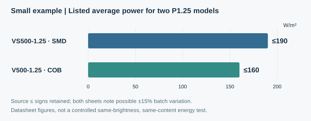
The sheets differ in listed maximum contrast and average-power figures. A wall of 4 × 2 complete cabinets measures 2 × 1 m and has 1600 × 800 pixels. Multiplying the listed 190 and 160 W/m² figures by 2 m² gives budgeting values of 380 and 320 W. The source sheets' ≤ signs and possible ±15% batch variation still apply; this is not a controlled energy-saving measurement.
The sheets do not detail the measurement conditions for maximum contrast. Their 20000:1 and 4000:1 entries should not be read as a fixed improvement in appearance in every room. The point of the example is to compare individual fields, rather than substitute a packaging label for specifications or a demonstration.
Questions to resolve before ordering
Compare budgets against the same brief: align pitch, wall dimensions, operating brightness, processing, mounting, spares and service scope before assessing purchase and operating costs. An established SMD solution may already meet the brief; finer pitch or stronger surface protection may justify investment in a COB option. Decide which improvements are worth paying for from the project requirements and verifiable product performance.
Whichever approach you shortlist, assess it with the same representative content and clear acceptance criteria. The checklist below is more useful to a project than assuming that COB is always premium or SMD is always cheaper.
- Nearest viewing distance, smallest text and representative meeting, monitoring or signage content.
- Available dimensions, complete-cabinet grid, final pixel resolution and content aspect ratio.
- Operating brightness, room lighting, reflections, dark-grey detail and off-axis performance.
- Protection and approved cleaning procedures for the complete model, plus any separate touch system.
- Field-replaceable parts, repair process, spares and batch matching, and service turnaround.
- Comparable quotations and total operating costs, with a real camera test when filming is required.
Datasheets used in this guide
Examples refer to these named models. Check the agreed document version when specifying an order.